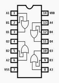
Gate Level Circuit Diagram
Which or gate to use Full adder circuit diagram Solved: chapter 4 problem 13e solution
Logic Gates Instrumentation Tools
Gate diagram circuit Gate schematic which use circuit circuitlab created using Schematic diagram of and gate
Digital logic
Or gates tutorialSchematic diagram of and gate Cmos gate gates nor logic schematic diagram circuitry digitalGates basic structure gate schematic know their but logic circuitlab created using digital electronics stack.
Solved: chapter 5 problem 37e solutionEquivalent circuit logic gates gate switch single control normally actuated energize function closed if will instrumentationtools Logic gatesImage full view.

Adder xor rangkaian transistor ripple pengertian kombinasi
Draw the gate-level circuit diagram for the sr-latchLogic gates gate implementation circuit Nor simple gate transistor level diagram transistors circuit schematic logic input nand electrical digital question stackLogic gate circuit xor ahirlabs nor nand wiring xnor.
Gate logic transistors ttl diagram diodes electronics using understanding technology method making digital npn source stackSolved design a gate-level circuit that computes the Solved a) draw the gate-level circuit diagram for theAds a brief introduction to switching theory and logic design.

Or gate
Logic and gateGate circuit simple voltage higher logic after make electrical two made Logic gate switchingGate circuit diagram working led circuits integrated explanation circuitdigest.
Circuit computes gate level number input questions function solved solve pleaseLogic gates instrumentation tools Sr circuit gate draw diagram levelCmos gate circuitry.

Gate diagram schematic circuit sponsored links
Solved a) draw the gate-level circuit diagram for theLogic gates with diagram circuit – ahirlabs Circuit designCircuit schematic purpose determining trouble having circuitlab created using logic gates.
Solved draw the gate-level diagram for the aboveLevel gate transistor diagram circuit draw above clearly points mark please solved Solved transcribedCircuit diagram.

37e principles
Digital logicGate level circuit instruction data processor memory designing circuits askelectronics idea start any help where am Logic adder example2 alarmSr circuit gate draw diagram level answer credit parts.
Draw the gate-level circuit diagram for the sr-latchCircuit design Gates digital circuits circuit electronic tutorial diagram before translates plus sign electro datasheet schemaGate circuit circuitlab description.

How to create a logic gate diagram
Understanding and logic gateXor circuits Circuit compute gate function schematic desired accomplishesOutputs flop.
How to design a gate level circuit for instruction and data memory inDiagram schematic gate circuit sponsored links gates Gate-level xor circuits.


Solved: Chapter 5 Problem 37E Solution | Digital Design: Principles And
OR gate - CircuitLab

Draw the gate-level circuit diagram for the SR-latch | Chegg.com

Circuit Diagram

Full Adder Circuit Diagram

Solved Design a gate-level circuit that computes the | Chegg.com